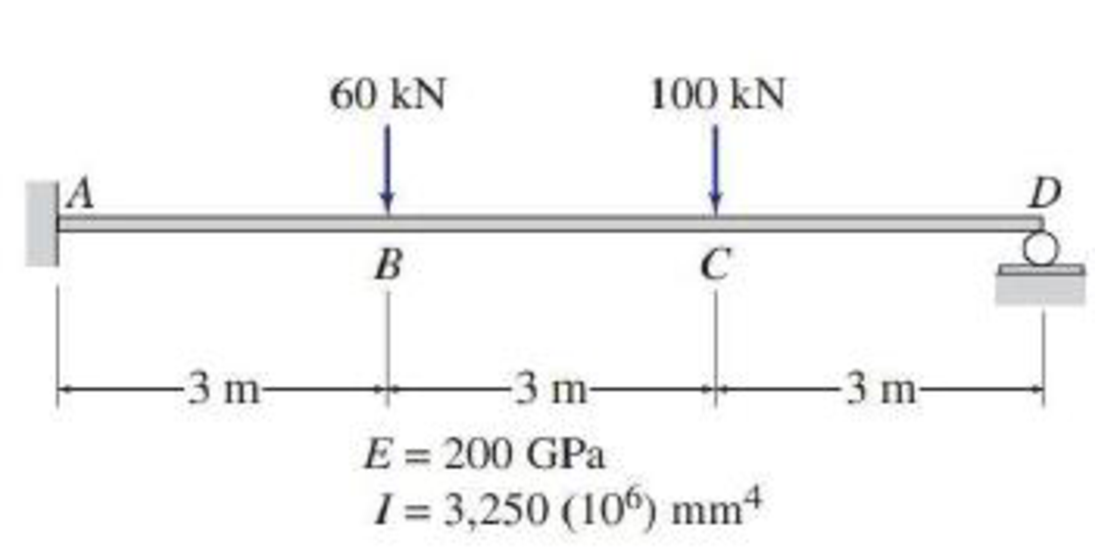
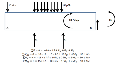
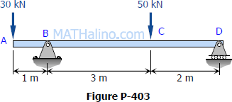
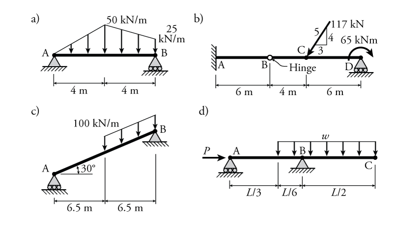
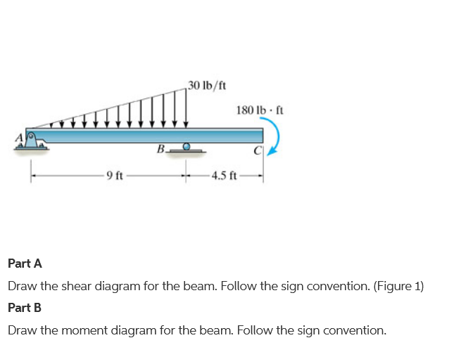
39 draw the shear diagram for the beam.
Transcribed image text: Problem 7.53 Part A Draw the shear diagram for the beam Click on "add discontinuity" to add discontinuity lines. Transcribed image text: Problem 7.53 Part A Draw the shear diagram for the beam. Click on "add discontinuity" to add discontinuity lines.
Draw the shear diagram for the beam. Draw the moment diagram for the beam. PLEASE HELP! NOT SURE WHAT I AM DOING WRONG! Image for Draw the shear diagram for ...
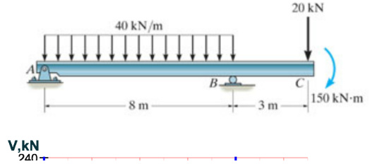
Draw the shear diagram for the beam.
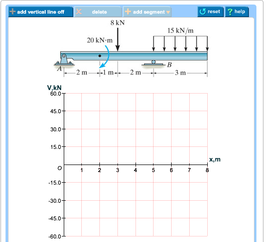
Shear Diagram. The shear of −2 kN at end A of the beam is plotted at x = 0, Fig. 6–16 c . The slopes are determined from the loading and from this the shear diagram is constructed, as indicated in the figure. In particular, notice the positive jump of 10 kN at x = 4 m due to the force B_y, as indicated in the figure. Moment Diagram. Draw the moment diagram for the beam. add vertical line off V(lb 1,000 750 500 250 250 -500 750 1,000. Show transcribed image text. Expert Answer. Part A Draw the shear diagram for the beam. Follow the sign convention. (Figure 1) Click on "add vertical line off to add discontinulty lines. Then click on "add segment" button to add functions between the lines. Note 1 - You should not draw an "extra" discontinuity line at the point where the curve passes the x- axis.
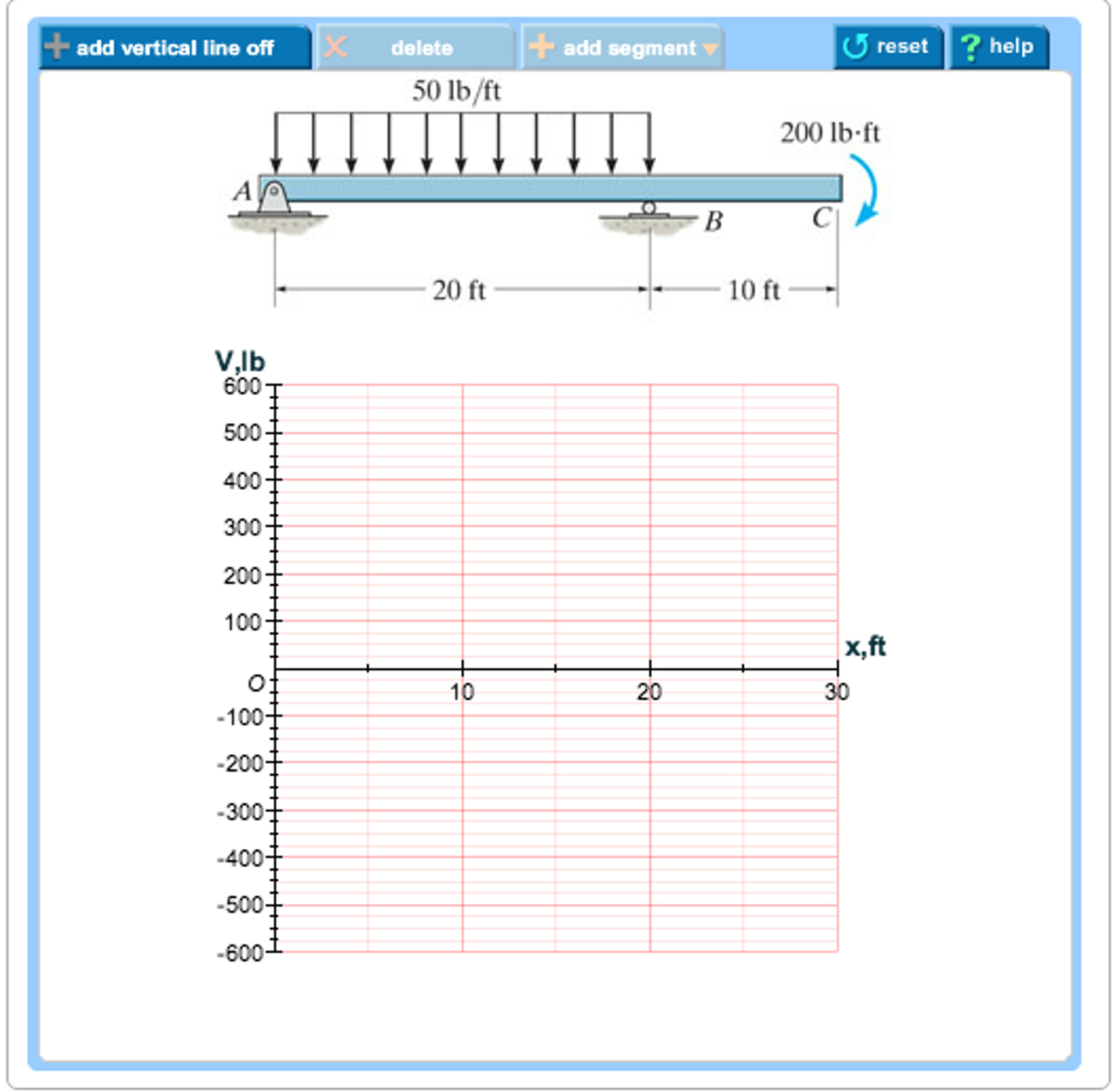
Draw the shear diagram for the beam.. Transcribed image text: Part A Draw the shear diagram for the beam. Follow the sign convention Click on "add vertical line off" to add discontinuity lines. Then click on "add segment" button to add functions between the lines, Note 1 - Make sure you place only one vertical line at places that require a vertical line. Question: 7.78 Draw the shear and moment diagram for the beam. This problem has been solved! See the answer ... The reactions have been determined as shown on the beam’s free-body diagram, Fig. 6–6 b . Shear and Moment Functions. A free-body diagram of the left segment is shown in Fig. 6–6 c . As above, the trapezoidal loading is replaced by rectangular and triangular distributions. Note that the intensity of the triangular load at the section is ... This problem has been solved! Draw the shear diagram for the beam. Draw the moment diagram for the beam. Determine the shear and moment throughout the beam as functions of x for 0 ≤ x ≤ 6ft (Please answer in terms of x) Determine the shear and moment throughout the beam as functions of x for 6ft ≤ x ≤ 9ft.
Shear and Moment Functions. Since there is a discontinuity of distributed load and also a concentrated load at the beam’s center, two regions of x must be considered in order to describe the shear and moment functions for the entire beam. M = ( − 2. 5 x 2 2 + 1 5. 7 5 x 2 + 9 2. 5) k N ⋅ m. Transcribed image text: Problem 7.70 Draw the shear diagram for the beam. Follow the sign convention. (Figure 1) Click on "add vertical line off" to add ... A Cantilever Beam Ab Supports Couple And Concentrated Load As Shown In The Figure Draw Shear Force Bending Moment Diagrams For This Bartleby. Draw The Shear Force And Bending Moment Diagrams For A Cantilever Beam Ab Carrying Uniform Load Of Intensity Q Over One Half Its Length See Figure Bartleby. Solved Express The Internal Shear And Moment In ... Part A Draw the shear diagram for the beam. Click on "add vertical line off" to add discontinuity lines. Then click on "add segment" button to add functions between the lines. Be sure to indicate the correct types of the functions between the lines, e.g. if in your answer the type of a function is "linear increasing slope" for the function that ...
(Figure 1) Part B Draw the moment diagram for the beam. Follow the sign convention. This problem has been solved! See the answer ... Shear Diagram. The shear at end A is −2 kN. This value is plotted at x = 0, Fig. 6–15 c . Notice how the shear diagram is constructed by following the slopes defined by the loading w . The shear at x = 4 m is −5 kN, the reaction on the beam. This value can be verified by finding the area under the distributed loading, Draw the shear diagram for the beam shown in the figure. Point Load. The load that has an influence only on a single point where it is acting on the beam is known as the point load, The magnitude ... Part A Draw the shear diagram for the beam. Follow the sign convention. (Figure 1) Click on "add vertical line off to add discontinulty lines. Then click on "add segment" button to add functions between the lines. Note 1 - You should not draw an "extra" discontinuity line at the point where the curve passes the x- axis.

Draw The Shear Diagram For The Beam Draw The Moment Diagram For The Beam Home Work Help Learn Cbse Forum
Draw the moment diagram for the beam. add vertical line off V(lb 1,000 750 500 250 250 -500 750 1,000. Show transcribed image text. Expert Answer.
Shear Diagram. The shear of −2 kN at end A of the beam is plotted at x = 0, Fig. 6–16 c . The slopes are determined from the loading and from this the shear diagram is constructed, as indicated in the figure. In particular, notice the positive jump of 10 kN at x = 4 m due to the force B_y, as indicated in the figure. Moment Diagram.

2 Group Solving Problem Draw The Shear Force And Bending Moment Diagrams For The Beam Shown U Homeworklib

Determine Reactions Draw Shear Bending Moment Diagrams Beams Shown Figs P161 P165 Using Mo Q33066256 Duepapers

For The Figure Below Draw A Draw The Shear Diagram For The Beam Follow The Sign Convention B Draw The Moment Diagram For The Beam Follow The Sign Convention Study Com
Calculate And Sketch The Bending Moment And Shearing Force Diagrams For The Horizontal Beam Shown In Figure Sarthaks Econnect Largest Online Education Community
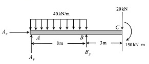
Draw The Shear Diagram For The Beam Draw The Moment Diagram For The Beam Home Work Help Learn Cbse Forum
Solved Draw The Shear Force Bending Moment Diagrams Of The Beam Shown In The Figure Below Taking Into Account The Given Loading Make Detailed Cal Course Hero
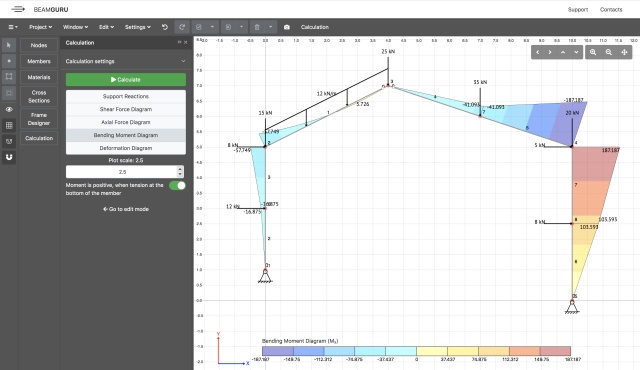
Beamguru Com Beam Calculator And Frame Truss Beam Calculator Online Draws Bending Moment Shear Force Axial Force
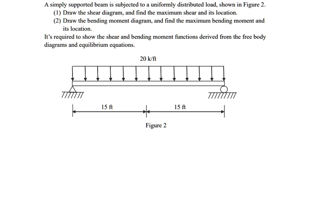
Solved A Simply Supported Beam Is Subjected To Uniformly Distributed Load Shown In Figure Draw The Shear Diagram And Find The Maximum Shear And Its Location Draw The Bending Moment Diagram And Find

For The Following Diagram Draw The Shear And Bending Moment Diagrams For The Beam Include The Homeworklib









0 Response to "39 draw the shear diagram for the beam."
Post a Comment